Case Report #3: DIY HUTU (Hop Up Tracer Unit)(Created on 07/27/2008 by Jawz)
Note:
Due to the urgency of this subject, I have published an incomplete Case Report about a DIY HUTU where the connection to a power source will be discussed at a later time. OP Red Invasion is nearing, and my intention is to help as many people as possible to get their guns ready for the night mission.
Therefore, this report will solely deal with the installation of the LEDs. Please keep in mind that LEDs must be connected to a resistor or you risk burning them up (speaking from experience). 
Consider this report "a work in progress" where the content and information can change. Any updates or changes will be published at the end of this paragraph:07/27/2008: No edits at this timeA. PurposeI have received many requests for detailed information about the construction and installation of a self-made hop up tracer unit (HUTU). Especially in view of the upcoming huge 1st-Sword event
Operation Red Invasion on August 28-30, 2008 (
http://1st-sword.com/forum/viewforum.php?f=12), tracer units are a mandatory part of the night game requirements that will enable all operators to fully submerge themselves into an unforgettable atmosphere!
1st-Sword leader Tank has already been installing HUTUs for past night games, but I have taken this concept which was published on different websites and on YouTube videos before and enhanced it in an attempt to match the performance of the 2nd generation TM Tracer Units and to improve accessibility and breakdown of the HUTU and gearbox.
2nd Generation TM TU:

 Disclaimer: Installing the HUTU requires intimate knowledge how to take down your gun and gearbox! Installation of the HUTU will require invasive and irreversible procedures that can cause damage to your gun! The author only provides information for educational purposes and is therefore not responsible for any damages derived from this knowledge. If you are not familiar with the internals of your gun or do not feel comfortable to perform any of the described procedures, it is highly recommended that you seek help from a professional!B. Concept
Some people would ask why constructing a HUTU and not a replica of the TM? After all, TM is the original creator to implement tracer units into airsoft guns, and their units work very well!
Indeed, many concepts have been suggested and attempts made to develop a cheap knock-off by using inexpensive LEDs. But all the designs failed usually due to lack of their ability to output enough energy that would illuminate tracer BBs sufficiently.
A quick calculation will show this dilemma: Let's assume a gun shoots at 400 FPS (feet per second) and at an ROF (rate of fire) of 20 BPS (bullets or BBs per second). Let's also assume that we would use a one foot long silencer-type tracer unit (TU) at the end of the barrel plastered with LEDs, which are already lit up and ready to make tracer BBs glow.
400 FPS means that a BBs will travel through the silencer TU in 1/400 sec., ie. in 0.0025 sec. This is a tremendously short period of time for anything to get illuminated. If we chose a HUTU, each BB would receive light for 1/20 sec., ie. 0.05 sec. at our assumed 20 BPS! That means the HUTU illuminates the tracer BBs 20 times longer than a silencer-type TU! Moreover, the LED light usually shines further down the feeding tube (especially with metail hop up chambers) making this design even more effective. So it's no wonder that the HUTU actually works! The silencer TU replica (based on LEDs)
may have a chance if more electronics were implemented to increase light output for example as a flash by overcharging LEDs, but this design would drive costs up making the original TM TU a better choice.
B.1. Design and PreparationThe idea of putting an LED into the hop up chamber is pretty simple assuming that you know how to break down your gun, use a soldering iron, and a drill: Drill a hole, plug in an LED, connect it to a battery, and then light up the LED.
Unfortunately, if you want to do it right, you need to take into account your ability to break down your gun in the future for maintenance or upgrading purposes. Therefore, you have to develop a modular design!
First of all, every gun type is different and hence, the most challenging part is the planning process how to route your wires, where to place your switch, where to install your LEDs, and where to put your quick connectors. A supposedly trivial part of the design is to find the right spot to accommodate your LEDs without interfering with the regular function of the gun. This sounds easier than it is sometimes, and due to space constraints, I can tell you right away that M14 owners are out of luck to install a HUTU! They have to either resort to the TM tracer unit or a modified magazine that hosts the LEDs and the battery. Unfortunately, the performance of the latter is pretty unsatisfactory compared to the HUTU.
After experimenting with many 3 and 5 mm LEDs in white, blue, and UV colors, I have come to the conclusion that the key to illuminating tracer BBs are super bright blue or UV LEDs. The dye of the tracer BBs seem to react best in the presence of UV light, though. UV light is defined as <= 400 nm wavelength. Unfortunately, small and space-saving (ie. 3 mm in size) UV LEDs are not very bright. The highest luminous intensity I found in that category was 3,000 mcd (millicandela). Although this intensity pales in comparison to the available 13,000+ mcd blue LEDs, UV LEDs perform admirably well, which is proof that the dye of the tracer BBs do indeed react to UV light best.
But whichever LED color you prefer, you need at least two of them.
Finally, you also have to plan what battery source you want to utilize for the LEDs: either the AEG's battery or a secondary battery source.
B.2. Quick Intro into LEDs: What is an LED?A light-emitting diode (LED) is a semiconductor diode that emits light when an electrical current is applied in the forward direction of the device, as in the simple LED circuit. The effect is a form of electroluminescence where incoherent and narrow-spectrum light is emitted from the p-n junction. (
http://en.wikipedia.org/wiki/Led)
The light emitting diode converts an elecrical current directly into light. Therefore, the light emitting diode (LED) is more efficient than many other light sources. [...] The forward voltage across a diode must exceed a threshold level before a current can cross the junction. For silicon, which emits a tiny amount of near-infrared, the threshold is 0.6 volt. For gallium arsenide, which emits considerable near-infrared, the threshold is 1.3 volts. (Getting Started in Electronics by Forrest M. Mims III; 3rd Edition; pg. 66)
You need to know some data about your specific LED before you should hook it up: The forward voltage (Vf) and the forward current (If). Of course, it's always good to know the wavelength and light intensity, but those are factors that are not need to calculate the value for the resistor. This information is available from its datasheet.
In order to choose the correct resistor value, you apply the following formula:
Resistance (R) = Voltage of battery forward voltage of LED (Vf)/forward current of LED (If)
Example: If you have an 8.4 V battery, your LED requires a Vf of 3.2 V, and the If is 20 mA (= 0.02 A), the calculation would look like this:
R = (9.6 V 3.2 V)/0.02 A
R = 320 ohm
... and the next available resistor value would be 330 ohm. This value would present a safe voltage for the LED. From personal experience, I have observed that LEDs are able to take a significant higher amount of voltage (supercharging the LED), although I'm pretty sure that this would reduce the lifespan of it. In a 24-hour marathon, I have used 4 UV LEDs with a 150 ohm resistor in conjunction with an 8.4 V NiCd battery. Result: The LEDs performed marvellously. So the choice is yours whether you opt to be on the safe side or if you want to squeeze out as much brightness as you can.
Before you grab your soldering iron, take a close look at the LED (picture courtesy of wikipedia):
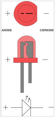
You can see that LEDs are polarized, ie. if you connect the LED in reverse, it will not light up. The best way to identify the polarity is to look for the flat side on the LED. This side by definition points towards the negative lead. Of course, you could identify the polarity by the lengths of the LED legs, but what would you do if the legs were already cut off and soldered to a board?
B.3. Required PartsDepending on the fanciness of your planned HUTU, there are more or less parts that you may require. The following parts list will allow for a modular HUTU design, which will facilitate the disassembly and reassembly of your AEG and simplify access to the gearbox for maintenance or upgrading purposes.
- 2x superbright blue (13,000+ mcd) or UV (3,000+ mcd) LEDs: please make sure you match or even exceed those values! At the time of this writing, RadioShack for example does not have suitable LEDs for this project!
- 1x Mini switch
- 1x Resistor: value depends on your battery voltage and LED
- Heatshrink
- 1 pair of JST connectors (quick connectors)
- Superglue
For a secondary power source, you would need to add a battery holder and your battery of choice, which has to give you more than 5 V of power to energize the LEDs.
B.4. Recommended Tools- - Soldering iron incl. accessories, such as wet sponge, solder with rosin core, desoldering braid, etc.
- Hot glue gun
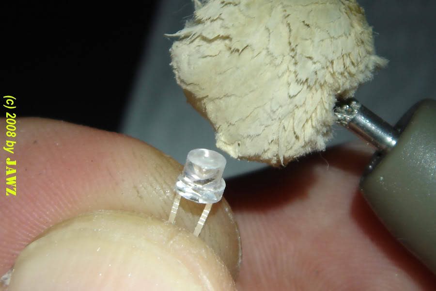
- Dremel or alike, including nylon disc, polishing wheel, acrylic polishing paste
- Drill with 7/64 drill bit
- Heat gun or simply a lighter
- Sharp knife such as a scalpel or Exacto knife
- Old towel or tissue to wipe your hands and protect your working area
- Optional, but is of huge help: Bright headlight
B.5. Installation Example on an M4 CQB Using the AEG BatteryThe following installation was done on an M4 guns with a crane stocks and contain pictures from different installation sessions. The installation principle remains with all guns, but a different approach to wire routing is of course necessary with different guns, and that's why proper planning part is so important.
B.5.1. Take Down Your Gun- I have included links in the References section with guides how to take down your specific gun. M14 guides are also included also I already mentioned that there won't be enough space for a HUTU.
- Put your gun down on a flat area and lay down your wiring on top of the gun. Try to make a mental picture of your final result.
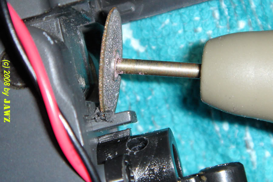
B.5.2. Remove the Upper Receiver and Inspect Your Hop Up SystemB.5.3. Remove Any Interfering PartsTo install the LEDs, you need to unscrew the cable holder and its corresponding rectangular column (highlighted in green).

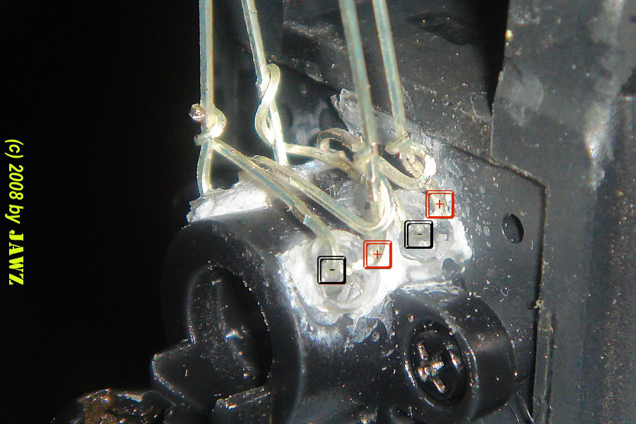
B.5.4. Mark the Drilling Holes and Use a 7/64 Drill Bit for the Holes- In this case 4 LEDs were used.
- Watch out not to push too hard when you are drilling. Otherwise, you may damage the walls of feeding tube when you suddenly pierce through the plastic.


- Use a sharp knife or scalpel to remove drilling flashes around the holes.